dudlington
Tried hooking up various Tacho,s to my 888SP4 with 996 SPS engined , twin injector with P8 computer.
I,m using the pin 4 on the P8 computer connector but strange things are happening.
First using what was sold as a 996SPS tacho I get the bike wanting to cut out when I touch connector 4 but also the revs are wrong. Secondly I then tried a tacho from what looks like ST4 with the same result.
Thirdly using an electronic tacho (Looks like from a Moto guzzi) I get on approx 2000 rpm a reading of 9/10,000 rpm.
Clearly both the first tacho,s are doing something wrong with the P8 as the bike wants to die and seems not to run cleanly. Probably these are tacho,s made for the 1.6 Marinelli computers
Third tacho could be a resistor needed (?).....but who knows.
Does anyone really know what to do as I,ve tried to find info but it is conflicting. I don,t want to touch ramdom pins in case something drastic happens. Pin 12 is NOT connected on this wiring loom.
Can anyone help ????
mikesps
A 996 SPS tacho has Ducati Racing written on the face, a 16M tacho has Ducati Corse on it. The signal comes from pin 12 so you will need to add a wire if there is not one there.
Mike
dudlington
Mike
I have the correct tacho (Ducati Racing) and have tried to use pin 12 direct from the computer but nothing happens.
The only combination that gets any tacho to work is the Guzzi tacho on pin 4............but it seems to give approx 4/5 times the necessary reading.
dudlington
So in for a penny , in for a pound. I,ve cut the back off the tacho as the glass was cracked anyway (Are,nt they all) to reveal the insides. I can see a small printed circuit board inside (Blue and red wire) but this only goes to the oil pressure light and is not connected to the workings of the tacho.
Now is there anyone out there that can tell me if this is the correct tacho for a P8 computer and how to wire it up so it works ?
griff851
Ah good timing. I have had to find out how they work as I have to fit a cheap Chinese one to the race bike, which fires the spark 3 time instead of once. Surprise after consulting doctor goggle, they work the same as analog volt meter. Find the pin with the changing voltage that's in sync with rpm. Pin 12 does as used by many. Then you need to find what voltage works in the rev range on the tacho by slowly feeding voltage into it that you've discovered previously. I think the circuit board must be a digital divider/multiplier thing. An SPA allows you to push a button for 1,2,4,6,8, clyinder engines, so pulses are being generated, due to reading you get when pushing the button.If you cannot simulate rpm, by doing this, then it must be dark magic at work or it's knackered.
My guess it will be in a higher rather than lower range. ie 6-7 volts rather than 5-6, as you got a signal out of the guzzi tacho, but death out of the other 2, but couldn't say for sure. Then all you have to do is put in a electronic dorgon that restricts or boosts your voltage to that range.
Pin 4 goes to the flywheel sensor. When you hooked up the tacho, all the voltage it produced was stolen or sent to earth, so the ecu went 'no rotation shut down fuel. It needs to sense 400 rpm before injectors are turned on I believe.
Sounds like if you want to play the plug cover has to come off. If you need to add a wire the plug pins are standard fuel injection pins available from auto electricians. Kids hair clips have a thin shiny bit of spring steel that can be doctored to remove the pins. Similar locking system to spade connectors in a block.
erthmvr888
The tach signal is a square wave, switched between +12V and ground by the ECU tach output. The signal from the engine rotation sensor is an AC quasi-sine wave with a missing portion , and is not suitable for triggering a tach, as it's level also changes dramatically at different RPM.
Go with the ECU tach output, just make sure your dash can cope with +12V signals. The ECU tach output switches every 90 degrees of crank rotation, that is, it does 2 complete cycles per engine revolution.
Duane Mitchell - UltiMap / FIM
not sure but this may help - someone was trying to put a Datalogger on his bike
Trav
erthmvr888
Here's the inside of a 94' 916 tach with a P8 - on the back the corsa tach and 94' 916 tach are marked 4P 12V might mean 4 pulse 12 volt
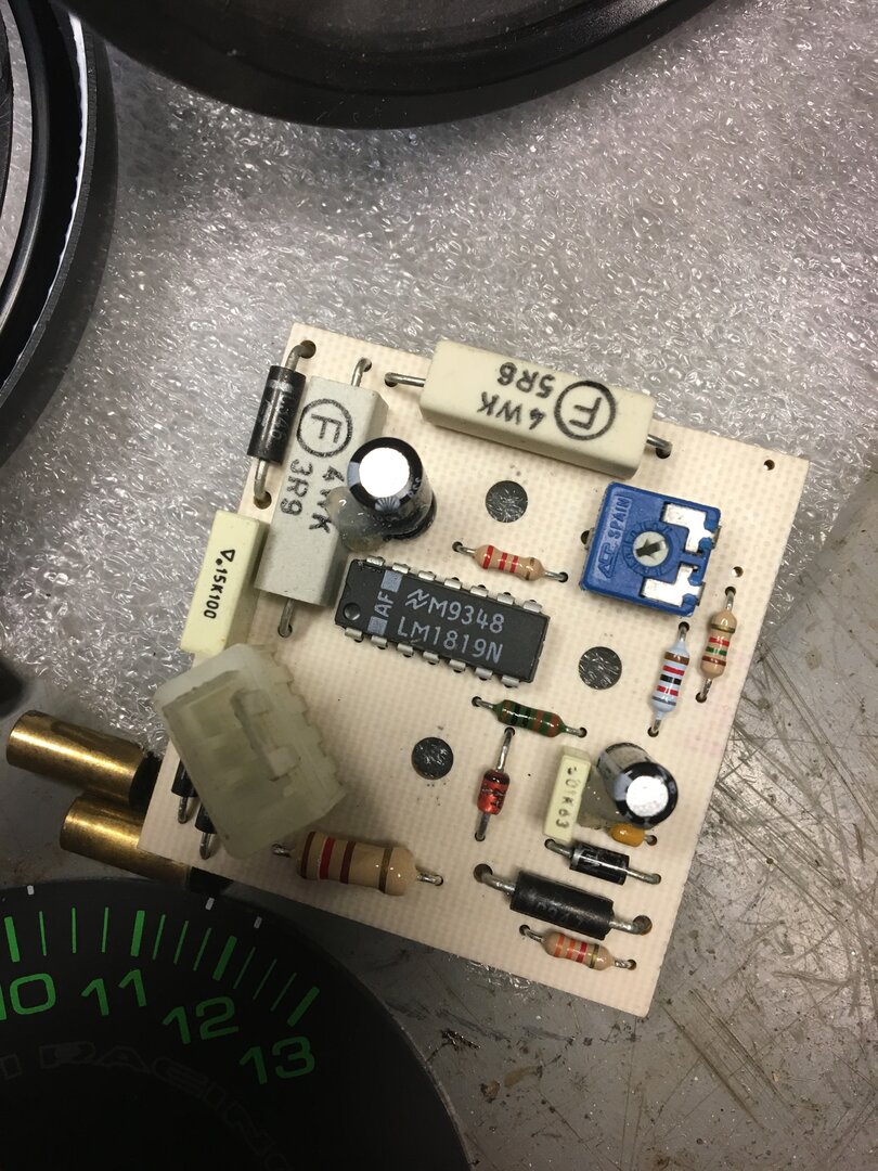
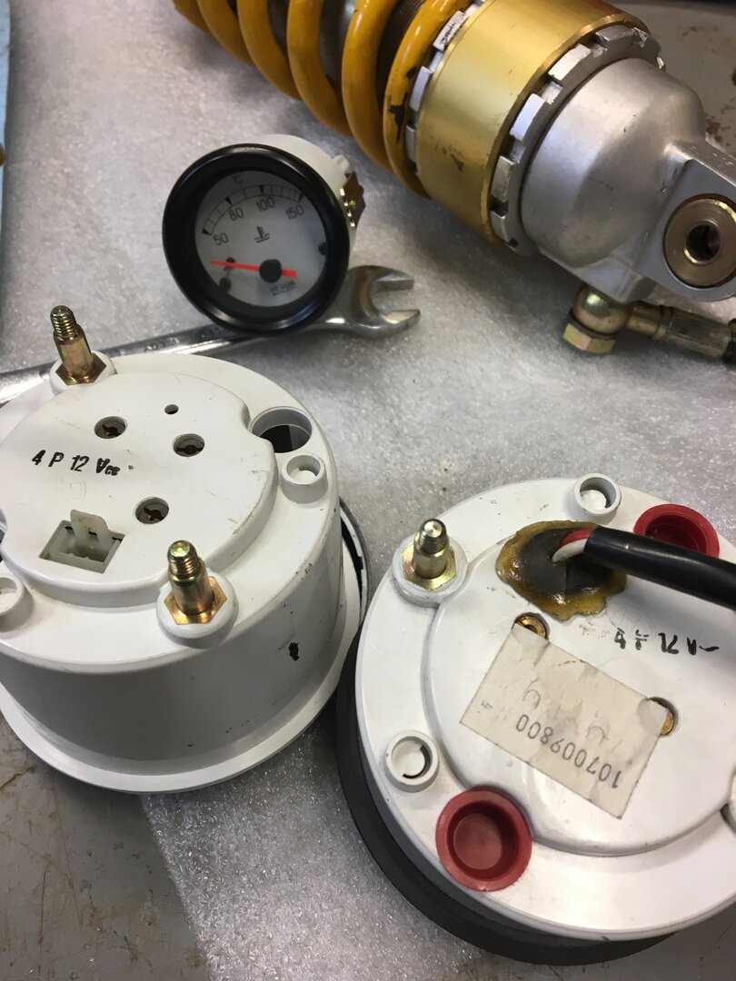
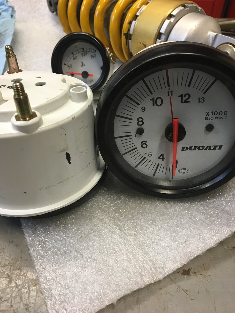
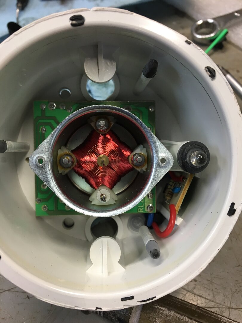
griff851
erthmvr888 wroteThe tach signal is a square wave, switched between +12V and ground by the ECU tach output. The signal from the engine rotation sensor is an AC quasi-sine wave with a missing portion , and is not suitable for triggering a tach, as it's level also changes dramatically at different RPM.
Go with the ECU tach output, just make sure your dash can cope with +12V signals. The ECU tach output switches every 90 degrees of crank rotation, that is, it does 2 complete cycles per engine revolution.
Duane Mitchell - UltiMap / FIM
not sure but this may help - someone was trying to put a Datalogger on his bike
Trav
Capt America to Ironman. 'It appears to run on some form of electricity! 😁
dudlington
erthmvr888 Many thanks for the photos and the info. It looks like my tacho is not the correct type for the P8 computer , hence why it will not work.
Griff851 Thanks for the info , so I need to use pin 12 and some kind of voltage regulator to fit in the range of the Guzzi Tacho (Probably 6V).
griff851
Guzzi's ran P8's, so did Fiat and Ferrari, you might get lucky. Years ago when I fitted my Spa I stumbled across a Guzzi fuel injection webpage and it had the almost full list of what the pins were for. And having just found it again I realise I have no idea why pin 12 came up. 139 and 140 are coil earths. 12,13 14 are blanks. Stand by, I try to write everything down, just have to find it. 😄
The tacho thing is a mystery to me as well, i'm Just flopping around in the dark as you are about why later model tacho's don't plug strait in. As the M1.6 is smaller I'm assuming it's about voltage of the signal, and hoping someone will chime in with the answers.
dudlington
So I have now found the correct wiring diagram for the 748/916 Biposto/SPS with P8 computer. Attached is a small section showing the RPM sensor part. Thick black line is the earth but then there are 2 thinner black cables that look like they are in some kind of dotted tube. The problem is one cable definately goes to plug 11 but the other could go to pin 28 but it does not seem to go far enough to definately indicate that. Ring any bells with anybody ???. Recently bought a dash unit (Including tacho) from a Laverda 668 that also runs a P8 computer and has exactly the same 3 pin connector on the back. Internals are supposed to be the same as the Ducati tacho and alot cheaper (If you can find one). I will open up and try to change the face to a Ducati one. Included is the full wiring diagram as well.
mikesps
The 98 biposto has a 16m ECU and only one RPM sensor, the 996SPS has two sensors so you may not have the correct wiring diagram. The 996SPS has one sensor for RPM and one for crank position. The flywheel has four lumps on it, so will give four signals per revolution. The other sensor senses the two machined teeth on the 44?? tooth timing gear.
If you want to a signal at engine RPM you could use an inductive pickup from an HT lead or try using the grounding wire from one if the coils to the ECU.
I think that the Laverda tacho should work but have not tried it.
Mike
griff851
Pin 11 is + power. Still can't find where I wrote down where I hooked up to.
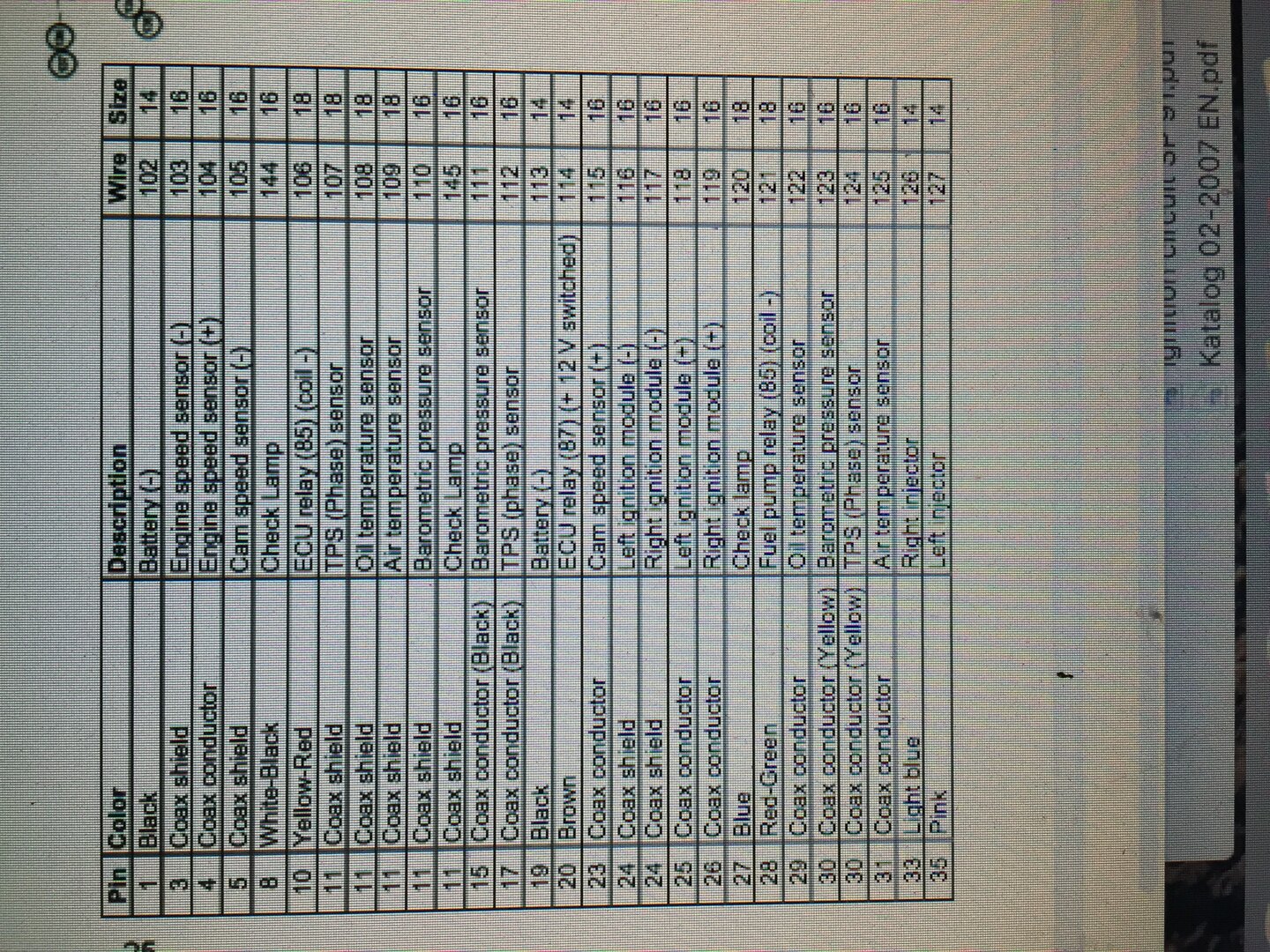
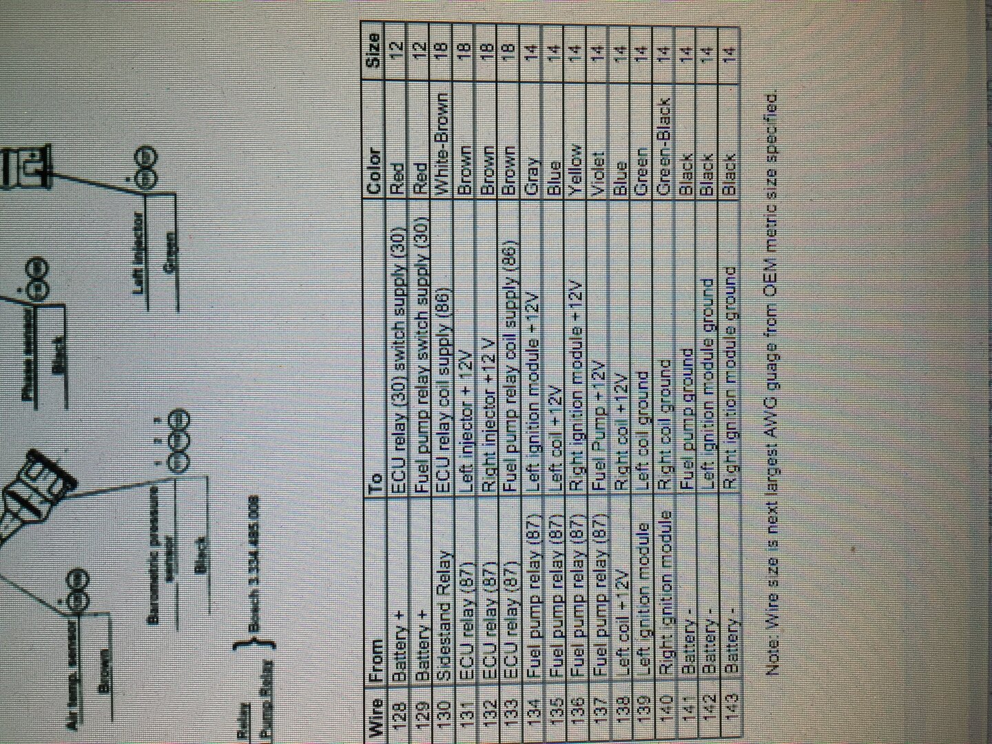
griff851
Pin25+, pin 1 - apparently.
JSR29
The wiring diagram you show is not the correct wiring diagram for a P8. See attached.(If I was successful attaching!) There's no such thing as a 748 P8.
If you are running a wiring harness from a P8 916, 916SPS or 996SPS a P8 tacho should work correctly no problem. If you are trying to adapt a 888 P7 wiring harness the sending pin appears to be pin 12 on the P8. I've never compared a P7 and P8 harness so I don't know if it's as simple as pulling positive and a ground and connecting the send to pin 12.
Tachs are another thing. Only a P8 tach will work with a P8 ECU. I have never seen any way to adapt a 1.6 to work with a P8. As far as I know there is no way externally to tell a P8 Tach from a 1.6. Cases and moulding marks are the same. "Ducati Racing" or "Ducati Corse" on the face is not a definitive indicator. Basically you have to KNOW that it's P8.
JSR29
Oh, and BTW, If you connect a 1.6 tach to a P8 ECU and harness it's inert. It doesn't sort of work.
dudlington
JSR29
Super thanks for the wiring..............I should have noticed the diagram I posted had only 2 injectors. Yours definately shows the right one. So Pin 12 it is with a P8 tacho , seperate + and - . I will try the laverda tach I have ordered and let everyone know how it goes. The Guzzi tach I have does not work with the above , nor does the 916 (M1.6) or the ST2/4 tach (Again M1.6).
Mr.R
I run a Laverda rev counter on my 851 fitted with a 996SPS loom and P8.
It works perfectly. Well after I reversed the outer wires in the 3 pin connector/plug.
Steve R
dudlington
So finally I can confirm.
Laverda electronic tacho works from pin 12 of the P8 ECU. The 3 wires are :
Red ...............+
Black ............. -
Green and white...........signal wire to Pin 12 of P8.
Many thanks to all that supplied info............it has been interesting.
dudlington
Seems I also got lucky with Moto guzzi electronic tach...........pin 23 gives the correct signal so that now works as well.